

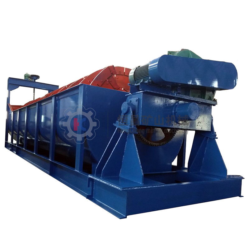
FG、FC型螺旋分級機 Spiral classifier
國家行業標準 JB/T 53601
一、用途
該系列分級機適用于礦石、非金屬物料進行脫水、脫介、脫泥和干濕式分級。
This classfiers suitable for dewatering,medium,drainaging amd spraying in ore clressing for medium and fine naterial wet and dry classifying in mine.
本機主要用于金屬選礦的生產流程中,依礦物顆粒泥降速度的不同,將14-325網目的礦石進行粒度分級,也可以以礦石中分出廢泥或用于礦砂的脫水。
Such machine is mainly used in the production flow of metal processing. According to the difference in sedimentation rate of mineral particles and mud, the particle sizes of ores with 14-325 meshes are classified. Waste mud or water for ore sand can be separated from the ores.
二、機器的技術規范
本機根據螺旋數量的不同,有單螺旋和雙螺旋之分,同時還有高堰式和沉沒式的區分,如溢流邊堰高于螺旋軸中心線,且低于溢流端部螺旋的外徑則為高堰式;如溢流邊堰高于螺旋軸中心線,同時還高于溢流端部的螺旋的外徑則為沉沒式:高堰式分級機一般用于100網目粒度以下的分級,沉沒式分級機一般用于200網目粒度以下的分級.
Such machines are divided into single spiral classifiers and double spiral classifiers. Beside, they are also divided into high weir spiral classifiers and submerged spiral classifiers. If the overflow edge is higher than the center line of spiral shaft and lower than the external diameter of spiral at the overflow end, the spiral classifiers are high weir ones. If the overflow edge is higher than the center line of spiral shaft and also higher than the external diameter of spiral at the overflow end, the spiral classifiers are submerged ones. High weir classifiers are usually used for the classification with particle size of below 100 meshes. Submerged classifiers are usually used for the classification with particle size of below 200 meshes.
三、技術參數
| 型號規格 Model | 螺旋直徑 Spiral Dia. | 螺旋轉速 Spiral Speed | 產 量Output | 配套電機功率Motor Power | 重量 Weight | |||
| 返砂量 Circulating Load | 溢流量 Overflow Quantity | 升降 Lift Lower | 傳動 Drive | |||||
| mm | r/min | t/24h | t/24h | kw | kw | t | ||
| 高堰式單螺旋分級機High-weir single spiral classifier | ||||||||
| FG-3 | Φ300 | 8.3-2.2 | 30-80 | 10-30 | 2.2 | 1.1 | 0.67 | |
| FG-5 | Φ500 | 8.5-15.5 | 143-261 | 32 | 2.2 | 1.1 | 1.6 | |
| FG-7 | Φ750 | 4.5-9.9 | 256-564 | 65 | 2.2 | 3 | 2.83 | |
| FG-10 | Φ1000 | 3.5-7.6 | 473-1026 | 85 | 2.2 | 5.5 | 4 | |
| FG-12 | Φ1200 | 5、6、7 | 1170-1600 | 155 | 2.2 | 5.5 | 8.54 | |
| FG-15 | Φ1500 | 2.5、4、6 | 1140-2740 | 235 | 2.2 | 7.5 | 11.68 | |
| FG-20 | Φ2000 | 3.6、5.5 | 3890-5940 | 400 | 3 | 11、15 | 20.45 | |
| FG-24 | Φ2400 | 3.64 | 6800 | 580 | 3 | 15 | 25.65 | |
| FG-30 | Φ3000 | 3.2 | 11650 | 893 | 4 | 22 | 40.9 | |
| 高堰式雙螺旋分級機High-weir double spirals classifier | ||||||||
| 2FG-12 | Φ1200 | 5、6、7 | 2340-3200 | 310 | 2.2×2 | 5.5×2 | 15.84 | |
| 2FG-15 | Φ1500 | 2.5、4、6 | 2280-5480 | 470 | 2.2×2 | 7.5×2 | 21.11 | |
| 2FG-20 | Φ2000 | 3.6、5.45 | 7780-11880 | 800 | 3×2 | 22、30 | 36.34 | |
| 2FG-24 | Φ2400 | 3.67 | 13600 | 1160 | 3×2 | 30 | 53.49 | |
| 2FG-30 | Φ3000 | 3.2 | 23300 | 1785 | 4×2 | 40 | 73.03 | |
| 沉沒式單螺旋分級機Submerged single spiral classifier | ||||||||
| FC-12 | Φ1200 | 2.5、4、6 | 1170-1630 | 120 | 2.2 | 7.5 | 11.1 | |
| FC-15 | Φ1500 | 2.5、4、6 | 1140-2740 | 185 | 2.2 | 7.5 | 15.32 | |
| FC-20 | Φ2000 | 3.6、5.5 | 3890-5940 | 320 | 3 | 11、15 | 29.056 | |
| FC-24 | Φ2400 | 3.64 | 6800 | 455 | 4 | 18.5 | 37.267 | |
| FC-30 | Φ3000 | 3.2 | 11650 | 705 | 4 | 22 | 46.2 | |
| 沉沒式雙螺旋分級機Submerged double spiral classifier | ||||||||
| 2FC-12 | Φ1200 | 3.8、6 | 1770-2800 | 240 | 2.2×2 | 7.5×2 | 19.61 | |
| 2FC-15 | Φ1500 | 2.5、4、6 | 2280-5480 | 370 | 2.2×2 | 7.5×2 | 27.45 | |
| 2FC-20 | Φ2000 | 3.6、5.5 | 7780-11880 | 640 | 3×2 | 22;30 | 50 | |
| 2FC-24 | Φ2400 | 3.67 | 13700 | 910 | 3×2 | 30 | 53.491 | |
| 2FC-24 | Φ2400 | 3.67 | 13700 | 910 | 4×2 | 37 | 65.283 | |
| 2FC-30 | Φ3000 | 3.2 | 23300 | 1410 | 4×2 | 45 | 84.87 | |
注:(1)表中C—代表沉沒式,G代表高堰式;2F—代表雙螺旋,F—代表單螺旋;(2)表載計算生產量是根據礦石比里,溢流粒度、螺旋轉數、螺旋直徑等因素按經驗公式計算得出。
Note: (1) In the table, C represents submerged type, G represents high weir type, 2F represents double spiral type, and F represents single spiral type. (2) The production capacity in the table is figured out based on empirical formula according to factors such as overflow particle size, revolution speed of screw and screw diameter in ore ratio.
四、機器的結構說明
3、總體說明
本機系由傳動裝置、螺旋(左、右)水槽、升降裝置、下部支座、潤滑裝置、排礦閥和進料口等部組成。(詳見附后總圖)
本機水槽成傾斜安置,其傾斜角大小根據工藝流程中設備配置情況確定,由傳動裝置帶動的螺旋(左、右)在槽內回轉,經磨細的礦漿從側面進料口進入槽內,則在槽的下端形成一個礦漿沉淀區,其表面積和容積決定于水槽傾斜角大小和溢流邊堰高度,低速回轉的螺旋能起一定的攪拌作用,礦漿經攪拌后,輕、細顆粒浮于上面成為溢流,由溢流邊堰溢出,流入下一道選礦工序;粗重的顆粒沉于槽底,成為返砂,由螺旋運輸到排礦口排出,其工作原理見圖1。
如果磨礦與分級是閉路循環作業,則由排礦口排出的返砂,仍進入磨機再磨細,分級機通常是與磨機配置在一起成閉路循環工作的。
IV. Structure Description
1. General Description
This kind of machine is composed of transmission mechanism, (left, right) spiral water tank, lifting device, lower support, lubricating device, ore discharge valve, feed inlet, etc (See the attached general drawing for details).
The water tank of this machine is installed obliquely. The angle of inclination is determined according to equipment configuration of equipment in the process flow. The (left, right) spirals driven by the transmission mechanism rotates in the water tank. The finely grained slurry enters the water bank from the feed inlet at one side and forms one slurry precipitation zone, whose surface area and volume depends on the value of the water tank’s inclination angle and the height of overflow edge. The spirals rotating at a low speed play a certain stirring role. After the slurry is stirred, the light and fine particles float above the surface and overflow from the overflow edge. Then they flow into the next working procedure of ore dressing. The heavy and thick particles sink into the bottom of the water tank and become return sand which is transported by the spirals to the ore discharge mouth for discharge.
If ore grinding and classification are closed loop operation, the return sand discharged from the ore discharge mouth still goes into the mill for further grinding. Classifiers normally form closed loop operation together with mill.
Function Diagram
1、傳動裝置 2、左螺旋 3、右螺旋 4、下部支座 5、升降裝置 6、水槽
1. Transmission mechanism 2. Left spiral 3. Right spiral 4. Lower support
5. Lifting Device 6. Water tank
4、主要部件結構說明:
(1)傳動裝置:Ф3000,Ф2400,Ф2000分級機是由電動機、聯軸節、減速器聯軸節圓柱和傘齒輪副構成;Ф1500,Ф1200分級機則由電動機、三角皮帶、減速器圓柱齒輪副構成;它帶動螺旋回轉。
(2)螺旋(左、右):由空心軸、支架、螺旋葉片、襯鐵等組成、上端支承在十字軸套內、下端支承在下部支座內、空心軸走直徑Ф500㎜以上的用二個半圓形通長鋼板焊接成,免除了由于橫向焊縫的焊接質量,使軸產生折斷事故。小直徑的空心軸(Ф325)采用無縫鋼管。當螺回轉時,螺旋葉面對礦漿起微小的攪拌作用,輕、細的顆粒由溢流堰口排出,況底的粗,重顆粒由螺旋輸送到排礦口排出。襯鐵采用耐磨壽命是重大關鍵問題,尚須進行研究解決。
(3)下部支座:因其長期浸沒在礦漿內工作,因此密封是關鍵問題,密封的好環直接影響軸承使用壽命,在設計上采用多層棉紗發瓣式盤根和高壓油脂雙重密封結構,并在潤滑裝置上配置手動干油泵,可以定期往軸承內壓注油脂,以保持其密封性能。
(4)水槽:由鋼極、各種型鋼焊接成。由于運輸等問題Ф3000,Ф2400,Ф2000分級機的水槽,在工地進行總裝焊接。水槽內盛有全部,并承受機器本身重量和全部負荷,為此支承水槽的地基設計分重要(結構要合適、基礎要牢固。)為避免因支承不當造成水槽變形影響機器的運轉起見,本機附有地基結構示意圖,可作為地基設計的參考依據。
(5)潤滑裝置:為善機器的潤滑條件,加強下部支座軸承的潤滑和密封性能Ф3000、Ф2400、Ф2000分級機故采用手動集中潤滑,配置了手動于油泵和操縱閥門,可以定期向各軸承內壓注油脂,潤滑操縱部分用戶可根據具體操作條件確定安裝在水槽的右側壁上或右側壁上,也可另外設置操縱臺Ф1200、Ф1500分級采用手動潤滑方式。
(6)放水閥:為了必要時能從水槽內排出礦漿,在水槽下部設有放水閥,可隨時將礦漿排出,正常生產時可關閥。
(7)升降裝置:它由電機、輪減速器、傘齒輪副、絲母、比等零部件組成,當分級機停止工作時,為避免礦漿內固體沉淀壓住螺旋,產生負荷損傷機件起見,以及檢修工作上的需要,故設有升降裝置。當分級機停車時必須把螺旋由水槽中提起,使大部分螺旋離開礦漿,為保證升降作業的安全,專備有行程終點開關,使升降行程能自行控制,其電氣原理圖參見圖2
另外還特設計有螺旋分級機轉動和升降聯動控制電氣原理理圖(圖6)當分級機停車時升降裝置啟動能自動將螺旋提升至一定高度,分級機工作時升降裝置把轉動能自動將螺旋下降至工作位置這樣可保持傳動零部件的壽命,防止空心軸因過負荷而折斷,。是否需要裝設聯動控制電氣裝置,用戶可根據具體條件確定、制造廠不供應本電氣裝置所需的零部件。
4. Structure Description of Main Parts
(1) Transmission mechanism: Ф3000, Ф2400 andФ2000 classifiers consist of motor, coupling, speed reducer coupling cylinder and bevel gear pair whileФ1500 andФ1200 classifiers consist of motor, V-belt, and speed reducer cylinder gear pair. The transmission mechanism drives the rotation of spiral.
(2) (Left, right) spirals: Spirals consist of hollow shaft, bracket, spiral vane, iron liner, etc. The upper ends are supported in the cross-shaft sleeves while the lower ends are supported in the lower support. Hollow shafts whose diameter is over 500mm are welded with two semicircular long steel plates so that shaft fracture due to poor welding quality caused by transverse weld can be avoided. For hollow shafts with small diameters (such as 325mm), seamless steel pipes are used. When the spirals are rotating, the spiral vanes stir the slurry slightly. The light and fine particles are discharged from the overflow weir while the heavy and thick particles are conveyed to the ore discharge mount for discharge. Anti-wear life of iron liner is very important. It needs further study.
(3) Lower support: As lower support long operates submerged in the slurry, its sealing is very important. The sealing of lower support directly affect the service life of bearings. In design, it is of the multilayer cotton yarn valve-clack type packing and high-pressure grease double seal structure, and is equipped with manual dry pumps on the lubricating device. It can fill grease to the inside of bearings on a regular basis to maintain its sealing property.
(4) Water tank: Water tank is welded through steel poles and all kinds of profile steel. Due to difficulty in transportation, the water tanks ofФ3000, Ф2400 andФ2000 classifiers are generally assembled and welded at the workplace. The water tank shall bear the weight of the machine itself and all load. Therefore, the design of foundation supporting the water tank is very important (the structure should be reasonable and the foundation shall be firm). To avoid the water tank becomes deformed due to improper supporting and thus affect the operation of machine, the diagram of foundation structure is attached for this machine which can serve as the reference basis for foundation design.
(5) Lubricating device: To improve the lubricating conditions of machines and better the lubricating and sealing property of lower support bearings, the lubrication method of manual centralization lubrication is adopted forФ3000, Ф2400 andФ2000 classifiers. It is equipped with manual dry pumps and operating valve and can infuse grease to the insides of all bearings on a regular basis. Some users can decide if the lubricating control console is installed along the left wall or right wall according to specific operating conditions. Or it can be installed otherwise. The lubrication method of manual lubrication is adopted forФ1200 andФ1500 classifiers.
(6) Drain valve: Drain valve is installed at the lower of the water tank so that slurry can be discharged from the water tank when necessary. During normal operation, the valve can be shut off.
(7) Lifting device: The lifting device consist of motor, wheel reducer, bevel gear pair, nut with thread, and other parts. When the classifier stops working, lifting device is installed with an aim to preventing the solid in the slurry from precipitating and pressing the spirals so as to damage machine parts as well as facilitating repair work. When the classifier stops working, the spirals must be lifted from the water tank to get most of the spirals away from the slurry. For the safety of lifting operation, stroke end switch is installed so that the lifting journey can be controlled automatically. See Figure 2 for Electrical Schematic Diagram.
Besides, electrical schematic diagrams for spiral classifier rotation and lifting linkage control are designed (Figure 6). When the classifier stops working, with the startup of lifting device the spirals can automatically be lifted to a certain height. When the classifier is working, the spirals can be automatically lowered to the working position during the rotation of lifting device to keep the hollow from being fractured due to overload. Whether to install linkage control electric device shall be determined by the user according to actual conditions. The manufacturer does not provide parts and components required by this electric installation.
Figure 2: Electrical Schematic Diagram of Lifting Journey Control of Lifting Device
RD-熔斷器 TA-停止按燈 SC-提升用接觸器
SXK-提升行程開關 JC-下降用接觸器 JXL-下降行程開關
JA-下降起動
RD – Fuse TA – Stop light
SC – Contactor for lifting SXK – Lifting journey switch
JC – Contactor for lowering JXL – Lowering journey switch
JA – Lowering startup


 English


